Create a PCB assembly using Gerber data
This topic describes a typical procedure to define a new assembly using Gerber data. FactoryLogix uses a series of wizards to guide you through the steps to create a new product or assembly in the NPI client application.
Gerber files commonly used in PCB manufacturing are machine programs for photo plotters. Essentially vector-based drawings of each layer of the PCB, these files require additional processing referred to as digitizing in order to be used in FactoryLogix. The Gerber digitizer in FactoryLogix has several tools to assist with the digitizing process.
There are two main types of Gerber data:
RS-274D - these files require a separate aperture list which could be one list for all the Gerber files or one list for each Gerber file
RS-274X - these files contain embedded aperture lists
Create a new assembly
When you create a new assembly, only a name, revision level, and process revision level are required. Other options allow you to assign a customer to the assembly and copy a BOM/CAD and/or a process definition from an existing assembly.
Log into the NPI client application.
Select Process Engineering
 > New Assembly.
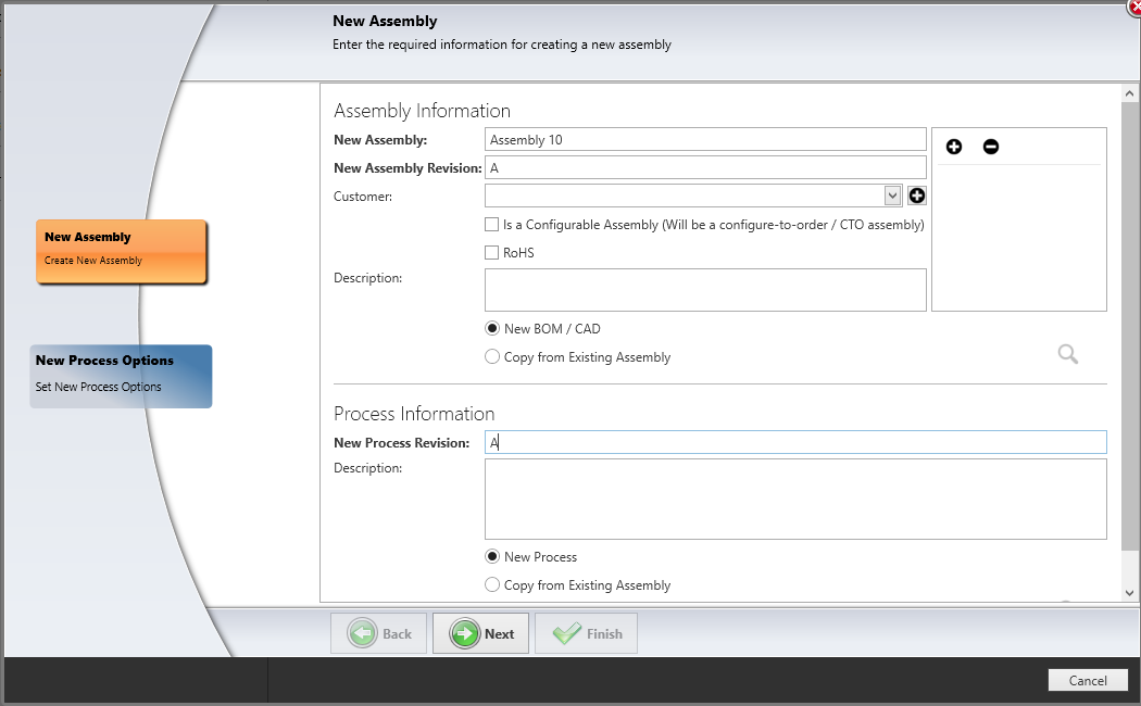
Enter a name for the New Assembly and a value for the New Assembly Revision level.
Note
Configure-to-Order (CTO) represents the ability for a customer to define the configuration of a product when they order it and a manufacturer to subsequently build that product configuration dynamically when they receive the order.
To associate a customer with this assembly, select a name from the Customer drop-down or select the Add
 button to add a new customer.
Note
If this assembly is a Configure-To-Order assembly, select the Is a Configurable Assembly (Will be a configure-to-order / CTO assembly) check box.
If this assembly is required to pass Restriction of Hazardous Materials (RoHS) compliance, select the RoHS check box.
Enter a Description for the assembly.
Note
Although entering a Description for an assembly is optional, a detailed description can be very helpful to others who may not be familiar with the assembly.
Select New BOM/CAD if you have a BOM file and CAD file for this assembly or select Copy From Existing Assembly to quickly reuse an existing BOM and CAD, then select the assembly from the list and select OK.
Enter a New Process Revision level.
Select New Process to create a new process definition for this assembly or select Copy from Existing Assembly to copy a process definition from an existing assembly.
Select Next.
Select new process options
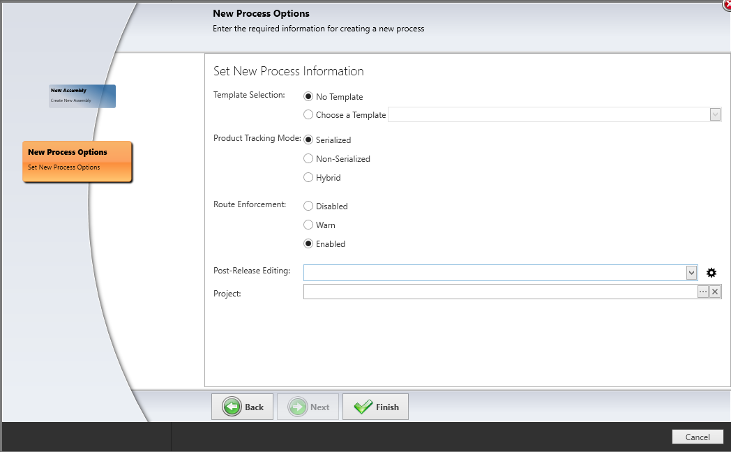
If you selected New Process in the previous topic, the wizard adds the New Process Options page where you can specify a template for the process definition, the product tracking mode, route enforcement options, a profile for post-release editing, and (if desired) a project to associate the new process definition with for the assembly.
On the New Process Options page, select a template for the process definition (if one is available), or select No Template if you plan to create a new process definition for this assembly.
Select the Product Tracking Mode: Serialized, Non-Serialized, or Hybrid.
Note
The Hybrid tracking mode combines both serialized and non-serialized tracking.
Determine if you need route enforcement for this assembly, then select Disabled, Warn, or Enabled.
If you plan to allow Post-Release Editing of this assembly, select a previously-defined Lock Down profile to apply from the drop-down.
Note
A Lock Down profile specifies the parts of a process definition that can be edited and the parts that are locked down (non-editable) after being released to production.
(Optional) To create a Lock Down profile for this assembly, select the gear
 button, select the Add button, enter a name for the profile, then select OK. Use the check boxes to select the parts of the process definition you want to lock down (that is, prevent others from editing), then select OK.
To associate this process definition with a project, select the Browse (...) button, locate and select the project, then select OK.
Select Finish.
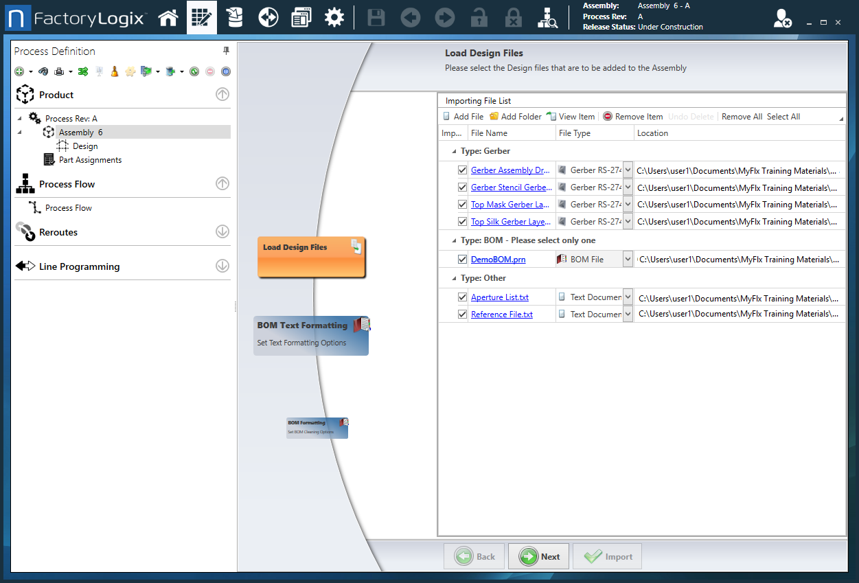
Load design files
The Load Design Files page is where you select a BOM, Gerber, and other supporting files for a new assembly. When you import files and folders, options at the top of the page are available to help you organize, select, and/or remove the necessary files and folders for the new assembly: View Item, Remove Item, Undo Delete, Select All, Remove All, Select Group, Remove Group. The available options depend on the files or folders selected on the page; use the check boxes to select or deselect specific files.
There are four general categories of files you can load:
BOM
ECAD
Gerber
Other
When you load design files, be sure to look in the File Type column and verify that each file type is identified correctly—especially BOM files that typically require cleaning and formatting. For example, a BOM may be loaded as an Unknown file type. Use the File Type drop-down to change design files to the appropriate (specific) file type for the product or assembly.
Note
For BOM files created in Microsoft Excel, FactoryLogix supports only Excel version 5.0 and higher files (*.xlsx format).
Tip
You can also load a *.zip design file—the system will extract and list all the files contained in the *.zip file automatically.
Under Importing File List on the right side of the page, select Add File, locate and select the BOM file for the new assembly, then select Open.
Note
If you already have a folder containing the desired BOM and other supporting files for the assembly, select Add Folder in Step 1, then locate and select the folder to import. (The wizard page that displays after the import step depends on whether you import files one-by-one or all at once in a folder or *.zip file.)
If the BOM file isn't recognized, it displays as type Other. To change the file type for the BOM, select BOM File and note the addition of a new button for BOM Formatting.
Important
If you don't select the file type BOM for your BOM file, you won't see or be able to use additional BOM formatting options!
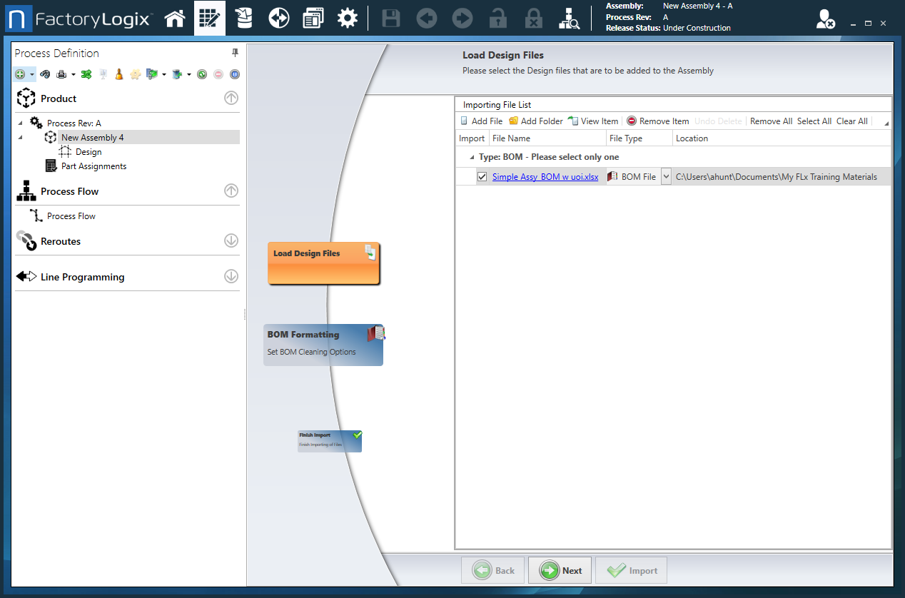
Select the Add File button, then locate and select the Gerber files for this assembly.
FactoryLogix automatically recognizes most file types and adds the imported files to a Gerber category.Add the remaining files or folders that support this assembly build. If the file types aren't recognized, use the File Type drop-down to assign the correct file types, then select Next.
BOM text formatting
When you import a text-based BOM file to use for a new process definition, the BOM Text Formatting page displays in the Process Definition wizard.
Under Parsing Options, do one of the following to format the text file:
Select Fixed Width to create fixed-width columns for the BOM data, then enter the desired column width.
Select Delimited, then use the drop-down to select the delimiter used in the BOM file to separate the various data values (comma, semicolon, colon, bar, tab, double tab, space, or double space). If a delimited character isn’t listed, you can enter it in the Delimited drop-down.
To save your text formatting for use with other text-based BOM files you import, select the Save
 button, enter a Template Name, then select OK.
Note
If you apply a template to a text-based BOM but then decide you don't want to use the template, select the Delete ![]() button.
button.
When you finish formatting the BOM text, select Next to move to the BOM Formatting page where you can make additional modifications.
BOM worksheet selection
When you import a worksheet-based BOM file containing more than one tab/worksheet to use for a new process definition, the BOM Worksheet Selection option displays in the Process Definition wizard.
After you select the BOM worksheet file, select BOM Worksheet Selection on the left side of the wizard page.
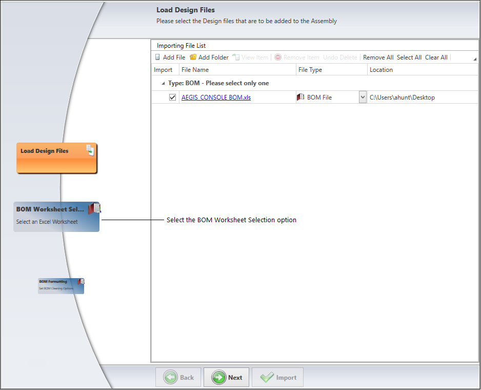
The BOM Worksheet Selection page displays, allowing you to select the desired BOM worksheet for this assembly. The following illustration shows an Excel file BOM with two worksheets: AEGIS_CONSOLE$ and Sheet 1$.
Under Worksheets, select the worksheet that contains the BOM data for this assembly.
The Preview pane on the right side of the window shows you what the worksheet BOM looks like before further editing.Select Next to move to the next wizard page.
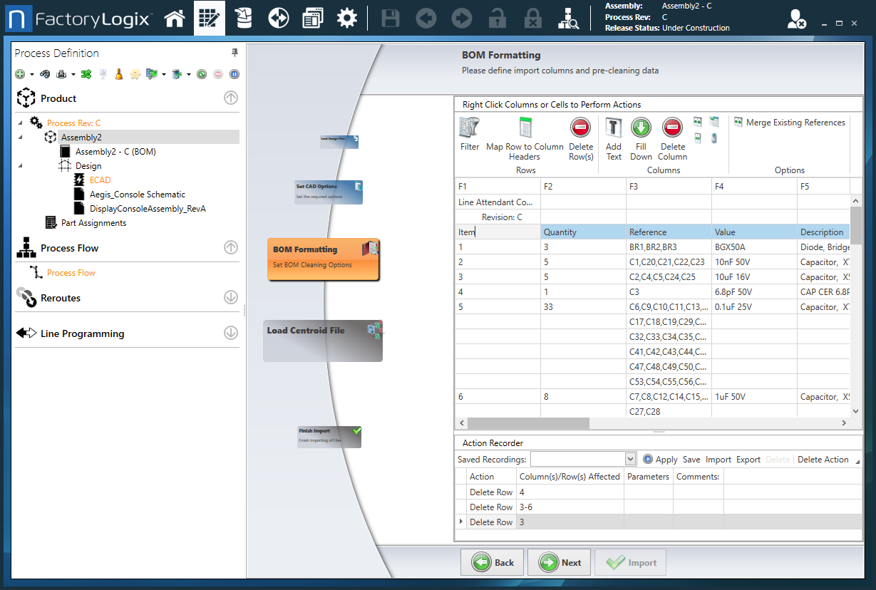
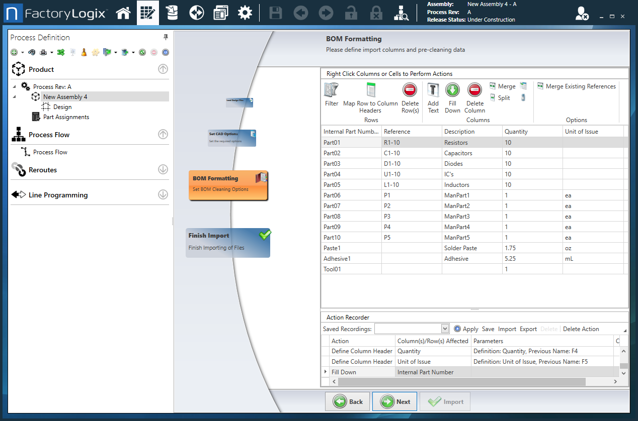
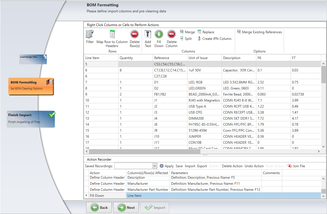
BOM formatting
When you create a new part or assembly in FactoryLogix NPI, the BOM Formatting page of the wizard lets you process complex BOM information into a more usable and organized format. The main goal of BOM cleaning is to define the fields (columns) to import from the BOM and remove unnecessary information to make the BOM more readable before you publish it.
FactoryLogix has powerful tools to help you clean BOM files of non-essential information and add formatting to make the BOM easier to read and use. When you format one type of BOM, FactoryLogix has the ability to "remember" the cleaning process—that cleaning process can be applied automatically in the future for similar BOM files, saving you valuable time and effort.
Important
Before making BOM formatting changes, we recommend you review the sub-topics in this section to understand the BOM cleaning tools, row and column editing options, and how the Action Recorder records and saves your BOM editing changes for future reuse.
On the BOM Formatting page, right-click a row, then select an editing option (Add Text, Edit Reference, Merge, Filter, and so on).
Right-click a column, then select a new column definition or remove a selected definition from the BOM.
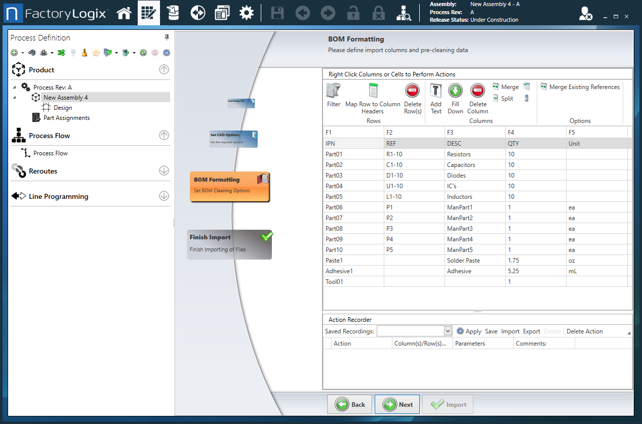
Select the row containing the column headers, then select the Map Row to Column Headers tool.
In the Map Column Headers dialog, select BOM rows to map to specific columns.
(Optional) After the columns are assigned, you can delete the header row automatically by selecting the Delete Header Row check box in the lower-left corner of the window.
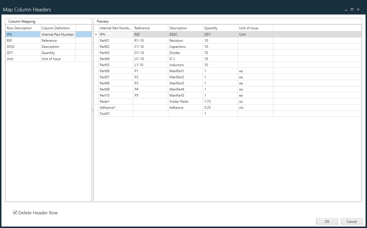
After you finish making the desired column mapping changes, select OK.
When you finish formatting the BOM file, select Next.
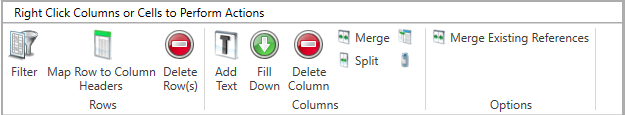
BOM cleaning tools and editing options
There are multiple tools and editing options available to help you format and clean up imported BOM data.
Tip
You can use the toolbar buttons or right-click rows and columns to access editing options.
Drag between two column headers to make a column wider or narrower.
Standard Cut, Copy, and Paste editing commands are available for selected cells when you right-click a cell (you can undo these actions using Ctrl+Z).
Edit rows
Editing rows | Description |
|---|---|
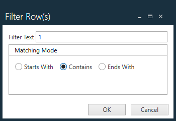
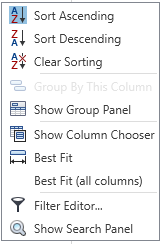
Filter | Removes all rows that contain the specified text from the selected cell in a column. Filter Matching Options specify the position of the filter text within the search:
|
Map Row to Column Headers | Maps the row of headers at the top of the BOM that define the data in each column to informational rows to define each column in the BOM.
Note You can also modify individual column definitions on the BOM Formatting page by right-clicking a column header and selecting a new column definition from the menu.
Note The Filter Editor is also used in DataMiner (Analytics) and the Trace window (Production) For details about using the Filter Editor, see Filter Gerber column data. |
Delete Rows | Deletes selected rows of data from the BOM. |

Edit columns
Editing columns | Description |
|---|---|
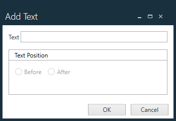
Add Text | Adds a prefix or suffix to the text in a selected column. Empty cells in the column will also contain the prefix or suffix automatically.
|
Fill Down | In some cases, BOM line items span multiple rows, but not every column's data is repeated in each row.
|
Delete Column | Removes a selected column from the imported BOM. |
Merge | Merges two or more selected columns of data into a single column. You can also remove the original columns after the merge. 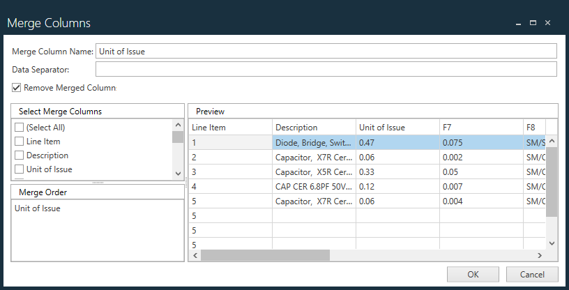 |
Split | Divides a single selected column into two or more columns and splits the column at the selected characters. 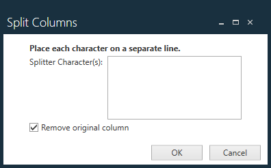 You can also remove the original columns after the split. |
Replace | Searches for and replaces the specified text from the selected cell to all the cells in the column that contain the specified text. You can match whole words only and/or match replacement text by case. 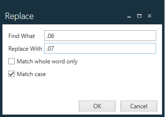 |
Create IPN Column | Allows you to create a new column from the selected column. The data in the new column may be appended with a prefix or suffix. 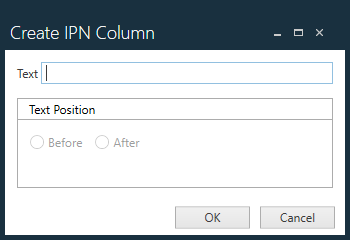 |
Merge Existing References | Allows you to merge the references from an existing BOM with the imported BOM (primarily used for non-PCB assemblies). |
Use the Action Recorder
During the BOM cleaning process, each change you make to the BOM is tracked and recorded automatically in the Action Recorder at the bottom of the BOM Formatting page. You can repeat previous actions on selected rows or columns using the commands in the Action Recorder (see the following table).
Command | Description |
|---|---|
Apply | Applies the selected action to a selected row or column of the BOM.
|
Save | Saves the current BOM cleaning actions as a recording (*.abt file) for use with other BOMs.
|
Import | Opens a dialog where you can browse to and select a recording (*.abt file) to import and use to clean the current BOM. When you import a recording file, it displays in the Saved Recordings drop-down. |
Export | Exports the current recording to a selected folder. |
Delete | Deletes the current BOM cleaning recording. |
Delete Action | Deletes the selected action from the Action Recorder. Select the arrow to the right of the Delete Action command (or drag to make the window wider) to display additional commands: 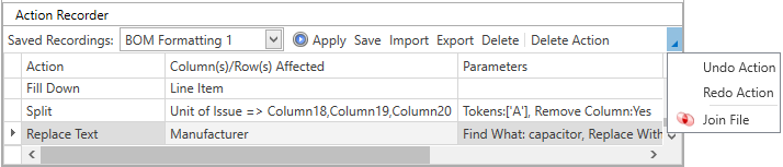 Undo Action - Reverses the selected action in the Action Recorder. Redo Action - Repeats the selected action in the Action Recorder. Join - Displays a dialog where you can join columns from a selected BOM with the current BOM. 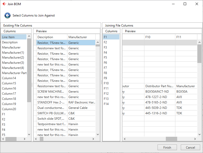 |
Set Gerber options
The Set Gerber Options page is used to format an aperture file (if loaded) for the purpose of defining the shapes of the pads.
If necessary, specify the RS-274D Parsing Options for the aperture file.
If you have an existing aperture file template, you want to apply, select it from the Saved Templates drop-down.
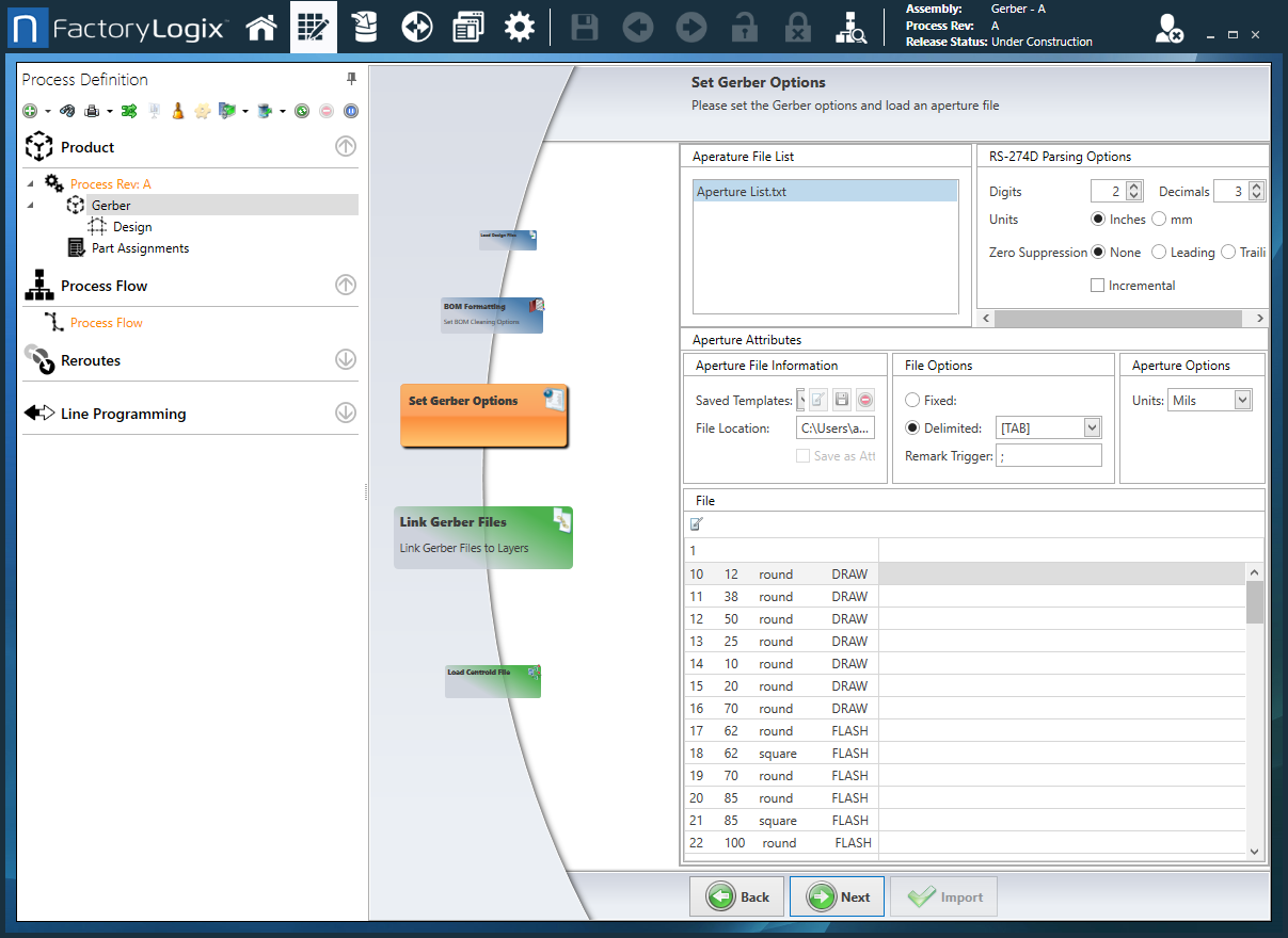
Under File Options, select the file format (Fixed or Delimited) and assign the Remark Trigger to hide rows in the aperture file that are not needed.
Under Aperture Options, assign the Units used in the file.
Under File, select the Edit button to make any necessary changes to the aperture file, then select Apply to save the changes.
Under File, assign the appropriate field (D-Code, X Size, Y Size, Shape) for each column.
To save your settings as a template, select Save As from the Saved Templates drop-down, name the template, then select Save Template.
Select Next.
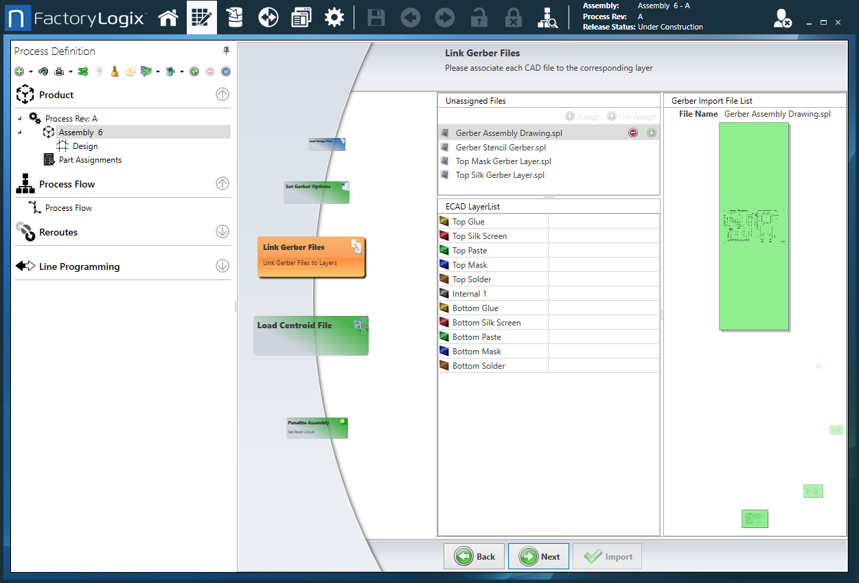
Link Gerber files
The Link Gerber Files page displays a list of the Gerber files you imported and a list of possible ECAD layers to which to link the files.
Drag a Gerber file from the list to the appropriate ECAD layer in the ECAD Layer List.
Continue mapping Gerber layers until all the required files have been assigned, then select Next.
Load the Centroid file
The Load Centroid File page is used when an X/Y Centroid is loaded to allow Reference Designators to be assigned during digitization.
Under File Options, set the file format (Fixed or Delimited) and assign the Remark Trigger which will hide rows in the Centroid file that are not needed.
Under Centroid Options, assign the Units used in the file and set the Top Side Filter and Bottom Side Filter used in the file.
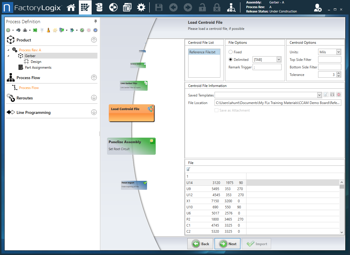
If you have an existing Centroid file template you want to apply, select it from the Saved Templates drop-down.
Under File, select the Edit button to make any necessary changes to the Centroid file, then select Save to save the changes.
Under File, assign the appropriate field (Reference, X, Y, Rotation, Mount Side, Footprint) to each column.
To save your settings as a template, select Create New from the Saved Templates drop-down, name the template, then select Save Template.
Select Next.
Panelize the assembly
The Panelize Assembly page is used when the Gerber files supplied are panelized to help specify the root image/circuit.
Under Layers, select the Active layer.
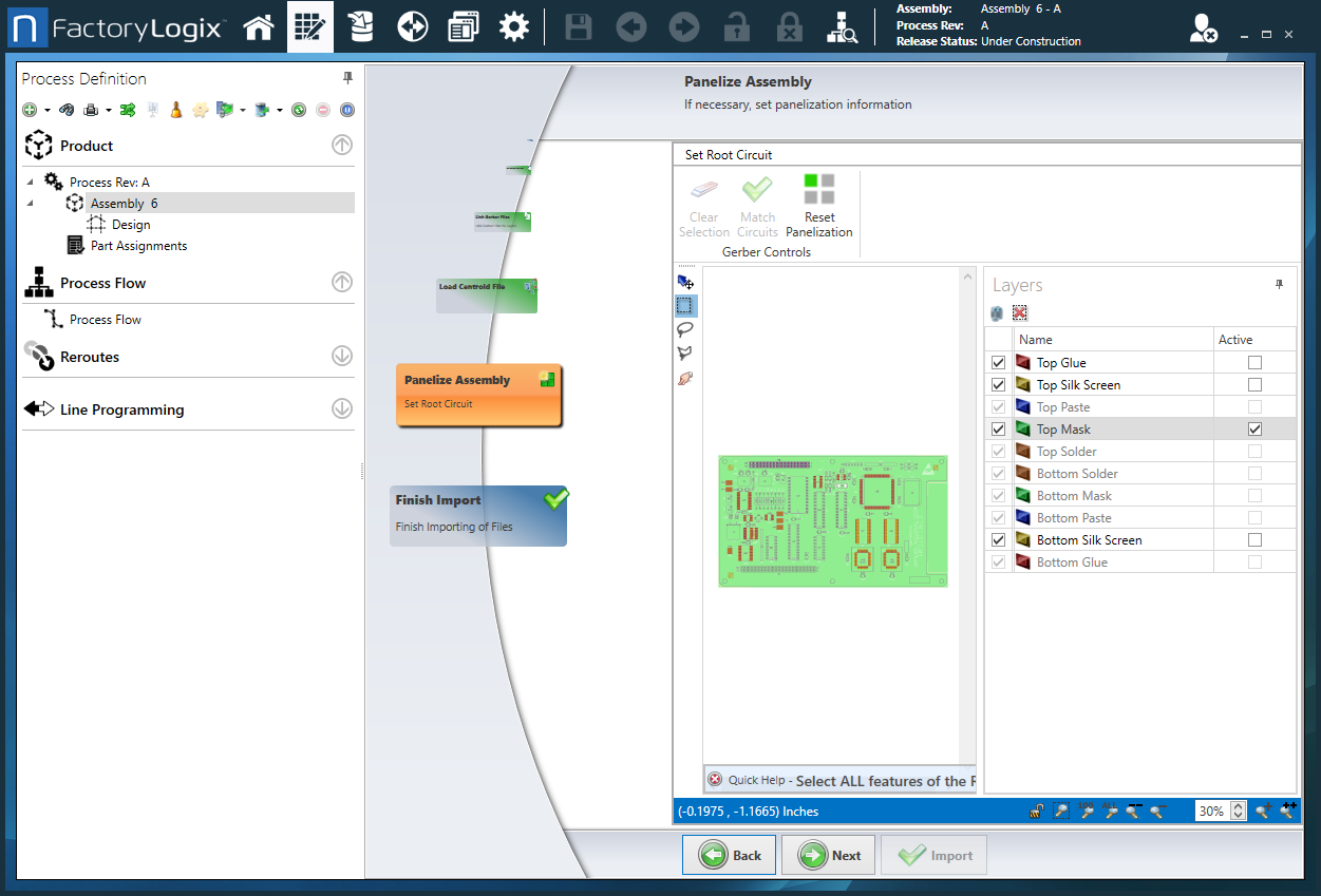
Use the Select Marquee tool (the lasso) to drag a rectangle around the root circuit, then select the Match Circuits button.
FactoryLogix will scan the Gerber data for matching circuits and highlight them.Select Next.
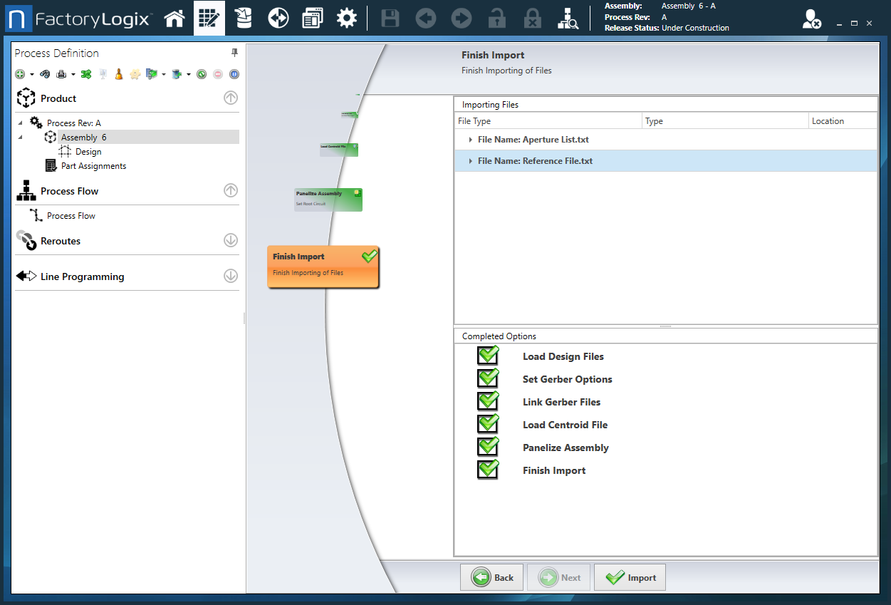
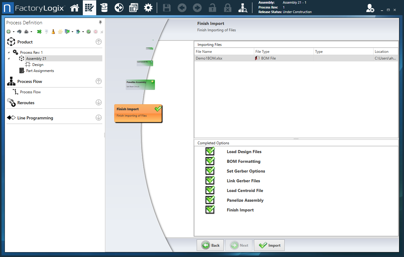
Finish the import
Use the Back and Next buttons to review your selections and changes for the assembly.
When you are finished making changes and you are ready to import the files for the new assembly, select Import.