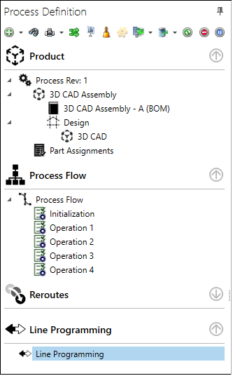
The toolbar buttons in the upper-left area of the Process Definition window allow you to customize a process definition and control various aspects of the process flow.
The following table describes the toolbar buttons and options in the Process Definition window.
Note
There are multiple ways to access some of the Add menu commands without using the toolbar such as right-clicking an item in the Process tree or selecting a command under Current Flow on the right side of the Process Definition window.
Toolbar item
Description
Add menu
Tip
You can quickly add operations to a process flow using commands on the right side of the Process Definition window under Current Flow.
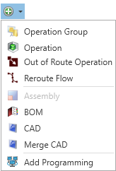
The Add menu contains options to add the following to a process flow when it is checked out for editing:
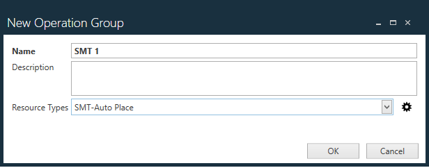
Operation Group - Adds an operation group. Enter a Name for the group , a Description (optional), select a Resource Type for the group, then select OK.
Operation - Adds an operation to a process flow.
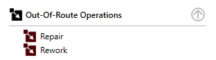
Out of Route Operation - Displays the New Out of Route Operation dialog where you can specify an out of route operation. Examples of out of route operations could include diagnostics, repair, rework, hold, disposition, or any other operation that might require an assembly to be detoured from the normal manufacturing process flow. For more information about out of route operations, see Out of route operations and reroutes.
Out of route operations are displayed in the Process Tree as shown here:
In an "any order" group, operations can be completed in any order. "Any-order" operations ensure that all processes within the any-order group are completed before allowing the assembly to pass on to the next operation in the flow.
An example of an "or" group might be where an assembly goes through an inspection process and there are two available inspection methods: automated and manual. The "or" group would allow the assembly to satisfy the routing requirements whether passing through the automated or the manual inspection operation. Operations can be completed in any order.
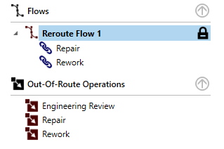
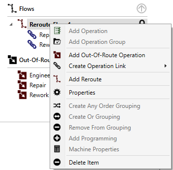
Reroute Flow - When you combine several out of route operations into a "mini" process flow, it is referred to as a reroute flow. The Reroute Flow command allows you to create a discrete reroute process flow when an assembly must be removed/detoured from the normal manufacturing process flow to one or more alternate operations.
When you select the Reroute Flow command, you are prompted to name the reroute flow, then it will display in the tree under Reroute Flow.
Right-click a reroute flow to display more commands allowing you to select and link out-of-route operations for the reroute flow.
There are also commands to group selected operations and operation groups in a process flow, allowing process engineers to define options such as "any order" operations and "or" groupings. Note that these options are also available under Current Flow on the right side of the Process Definition window.
BOM - Allows you to load additional BOM files by selecting BOM from the Add menu.
CAD - Allows you to load additional CAD files by selecting CAD from the Add menu.
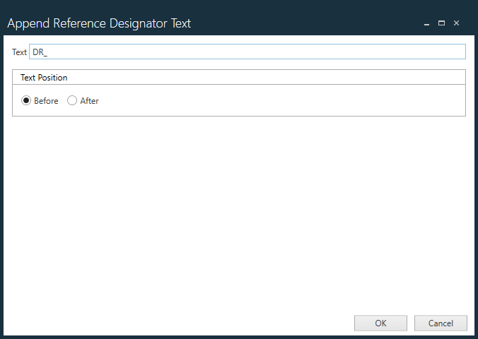
Merge CAD - Allows you to select a secondary ECAD file to merge/append to the existing ECAD for the selected process revision. This command might be useful if you have two different circuits and want to have them on the same panel, for example. When you select a secondary ECAD file, a dialog prompts you to append text to the reference designators in the secondary ECAD file so you can more easily differentiate the reference designators and avoid duplicates between the two circuits.
Add Programming - Displays a dialog where you can set up lines or machines for machine programming.
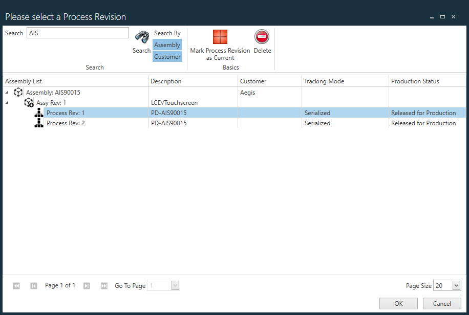
Select Process
Select the Select Process button on the toolbar to display the Please Select a Process Revision dialog where you can search for a process revision by assembly or by customer. You can also select a process revision and mark it as Current or delete a selected process revision in this dialog.
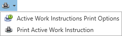
Print
Select the Print command from the toolbar to display these printing options:
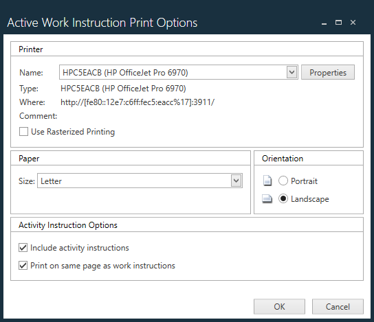
Active Work Instructions Print Options - Displays a dialog where you select how you want to print Active Work Instructions.
Select the desired printer properties and options.
Under Activity Instruction Options, select Include activity instructions to include text instructions for activities when printing.
Under Activity Instruction Options, select Print on same page as work instructions to print activity instructions on the same page as the Active Work Instruction to include text instructions for activities when printing.
Note
Select Rasterized Printing to print the Active Work Instruction as a bitmap.
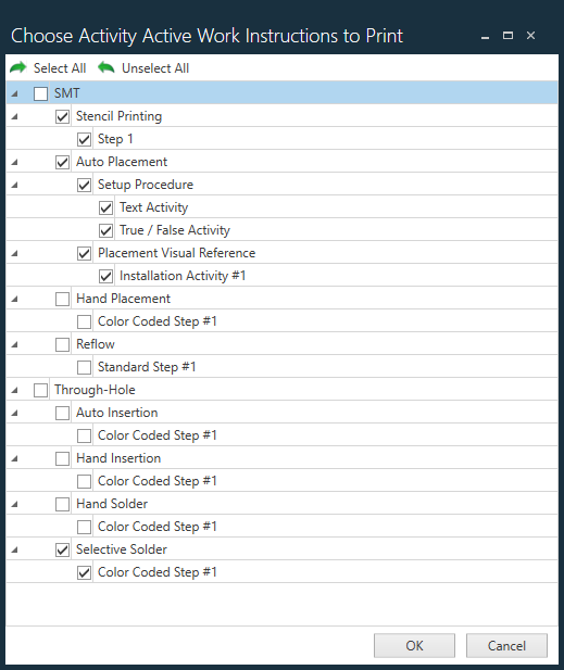
Print Active Work Instruction - After you set up all the desired Active Work Instruction printing options, select this command to print Active Work Instructions. When you select the command, a dialog displays where you select the specific Active Work Instructions you want to print, then select OK to begin printing.
Auto Route Part Assignments
Part assignments in FactoryLogix are based on resource types. A resource type specifies the resources used by a particular machine and is used specifically with xLink adapters.
Part numbers in the Part Library may have one or more assigned resource types.
Operations in process flows may have one or more supported resource types.
Select the Auto Route Part Assignments toolbar button to automate the routing of part assignments based on their resource type. (You can create and manage resource types in the Templates and Standards > Factory Resources area of NPI.) Once a BOM is published in FactoryLogix, the system will automatically assign all parts with resource types defined to the first operation that supports the defined resource type.
Auto-routing is controlled by the global option Auto Route Materials in NPI (System Configuration > Settings). When the option is set to True, part assignments will be auto-routed based on their resource type when you select the Auto Route Part Assignments toolbar button.
Note
You can also create and manage resource types in the Update Operation dialog using the Edit Resource Types button (the gear). This dialog is often the most convenient location for setting up the Auto Route feature. (To display the dialog, right-click an operation in the Process tree and select Properties.)
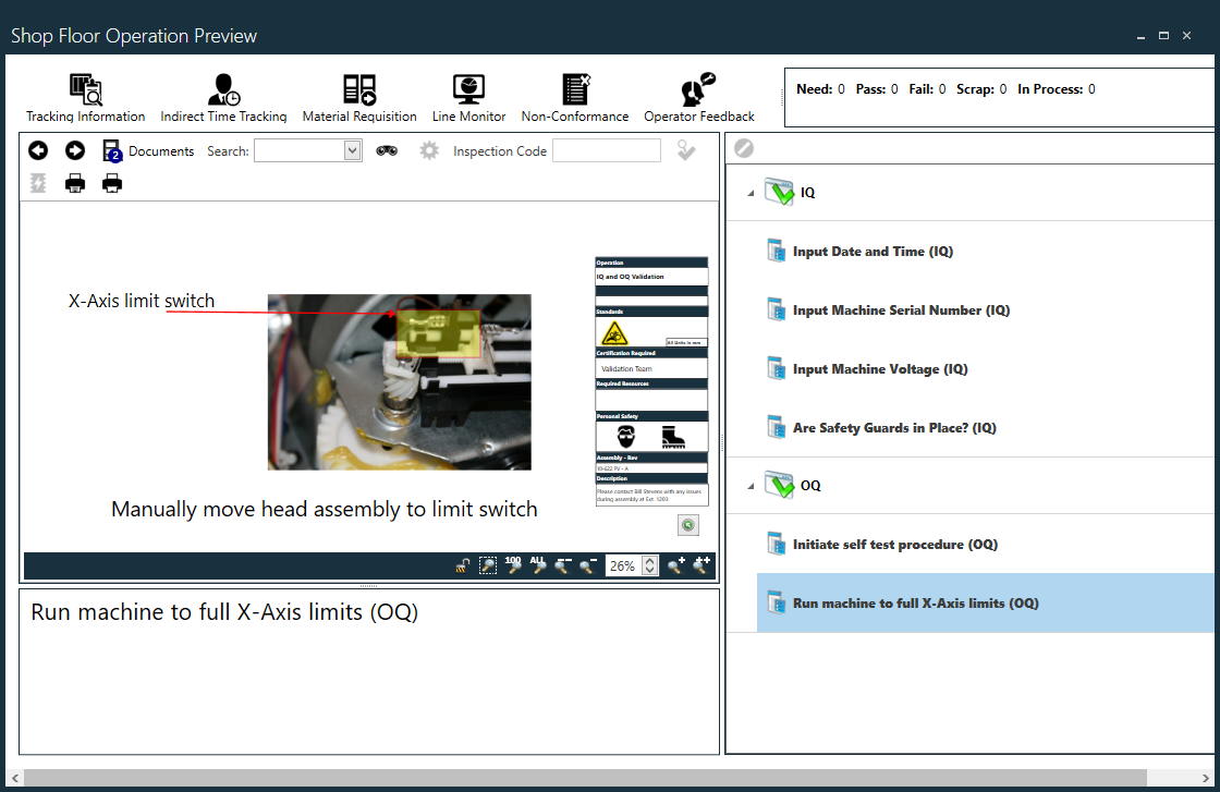
Show Shop Floor
Select the Show Shop Floor toolbar button to display a shop floor preview of the currently-selected operation. This preview is what the shop floor operator will see in Production for the operation.
In the Shop Floor Operation Preview window, you can step through each of the operation's steps and activities, review the visual aids and Active Work Instructions. You can also review and modify details about the selected operation including:
Tracking Information
Indirect Time Tracking
Material Requisition
Line Monitor
Non-Conformance
Operator Feedback
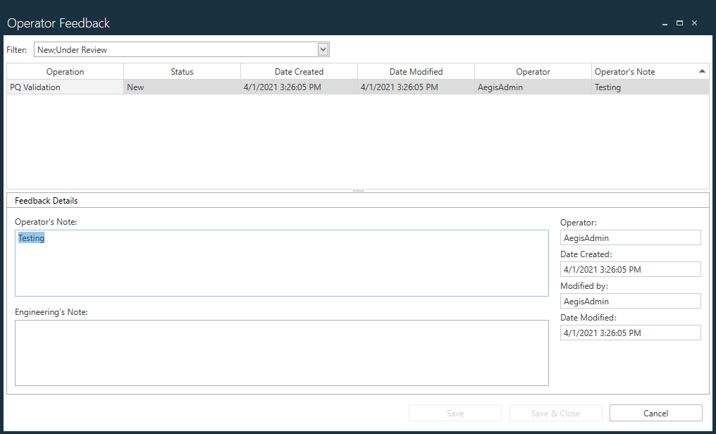
Operator Feedback
Select the Operator Feedback toolbar button to display operator feedback about the selected operation during production. Engineers' notes are also included in the dialog. This is the area where operators and engineers can add notes about the operation and filter the operator feedback by type.
Filter options for an operation include New, Under Review, Reviewed, Closed, and Ignore.
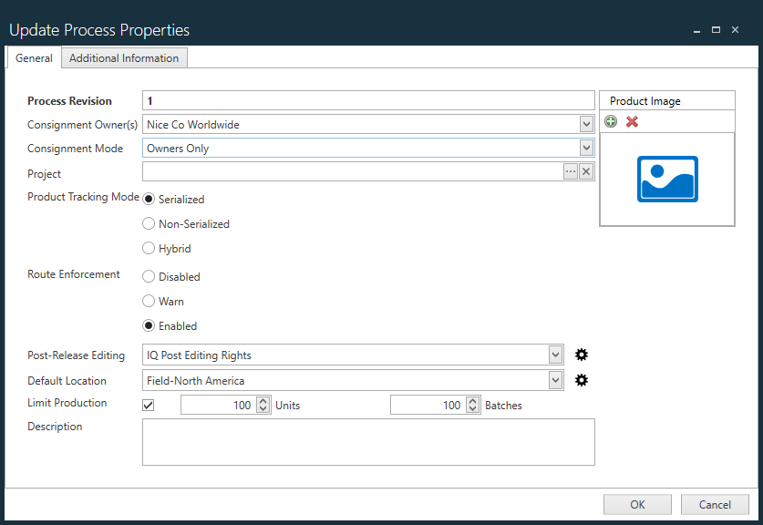
Properties
Depending on what is selected in the Process Tree (a process or an operation) selecting the Properties toolbar button displays one of the following dialogs:
In the Update Process Properties dialog on the General tab, you can change the process revision level, route enforcement, associate a project with the process revision, and modify or update other process-specific information for the selected process.
The Additional Information tab displays the revision history for the selected process including:
Revision sequence number
Revision name
Date created
The FactoryLogix user who created the revision
Note
When a custom field is defined for a process, a second property is also required that identifies whether a value is required for the process to pass sign-off approval (or will be allowed to be released to production when the process doesn't have an explicit approval process assigned to it).
If any process custom fields are defined, the field values are displayed in the revision history on the Additional Information tab. Once a process is approved (or released to Production if no process approval is defined), any previously-custom field values will be locked down and you can no longer modify those values. See Define custom fields for more information.
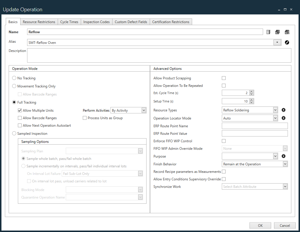
In the Update Operation dialog, you can view and change the properties for the selected operation.
Template Processing
Tip
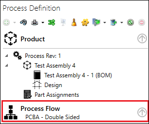
If you select a template to create a new process definition, the template file name displays in the process tree under the Process Flow heading:
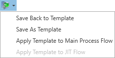
Selecting the Template Processing button to display this drop-down:
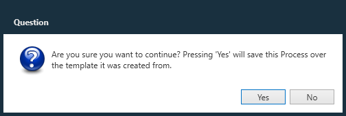
Save Back to Template - When you start a process flow definition using a previously-saved template and then make changes to the process definition, the Save Back to Template command allows you to save the modifications you made and overwrite/update the original template.
Warning
When you select the Save Back to Template command, the original template you used to create the process definition will be overwritten with changes you made to the current process definition.
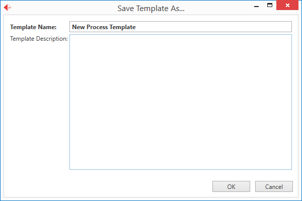
Save As Template - Displays a dialog allowing you to save the current process definition as a template.
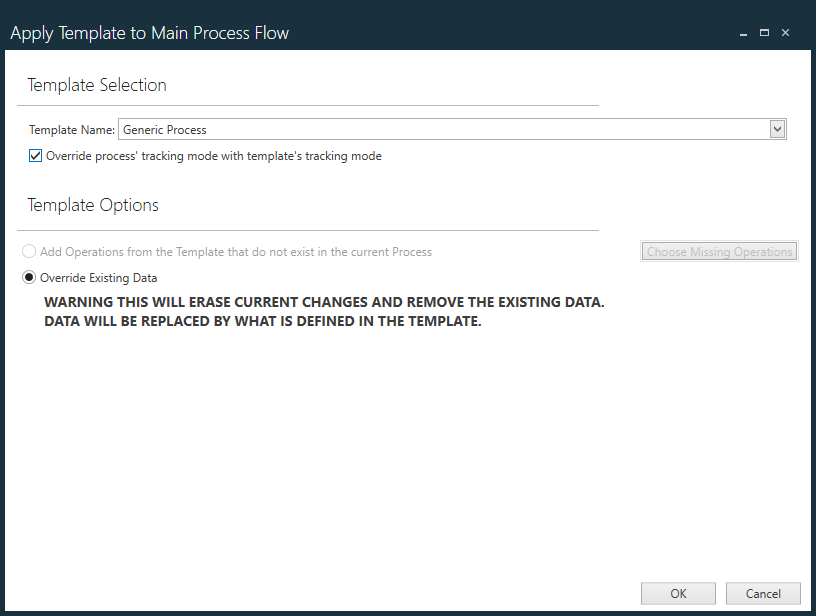
Apply Template to Main Process Flow - Displays a dialog where you can select a different template to apply to the current process definition.
Note
If you save the current process flow as a new process template, that process template is not yet assigned to the current process flow. You must apply the process template by selecting the Apply Template to Main Process Flow command in the Template Processing menu to assign the template.
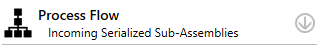
The template assigned to the current process flow always displays under Process Flow in the tree on the left side of the Process Definition window as shown in the following illustration.
Template Name - Use the drop-down to select the desired process template to apply to the current process definition.
Template Options
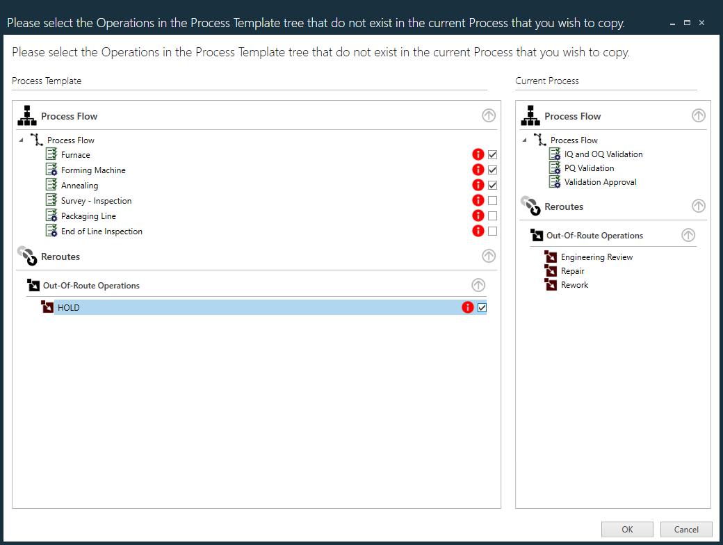
Add Operations from the Template that do not exist in the current Process - Displays a dialog that allows you to select only specific operations in the selected template to apply to the current process definition.
Override Existing Data - Overrides everything in the current process definition and applies everything in the template to the current process.
Warning
Before selecting the Override Existing Data option, ensure that you want to remove/override all existing data from the current process and apply everything in the template to the current process. You cannot reverse/undo an override of this type!
Export Process
Select the Export Process toolbar button to display a menu with the following commands:
Export Process to File - Displays a dialog where you can name and save the current process as a *.flxp file.
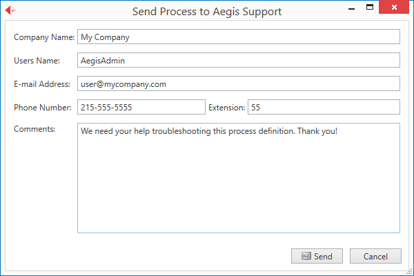
Send Process to Aegis - Displays a dialog where you can enter details about the process definition, your contact information, and the type of assistance you require. When you select Send, the process definition *.flxp file is sent to Aegis Technical Support for review.
Note
The Send Process to Aegis command is only enabled if your administrator previously set up a SMTP mail server for you in NPI > System Configuration > Settings (General category).
Refresh Status
Refreshes the data for the process definition after you make changes.
Delete Item
When available, deletes a selected item in the Process tree (a BOM file, for example).
Place Operations/Activities On Hold
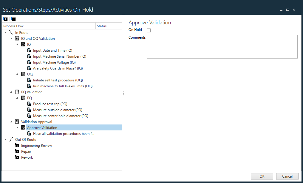
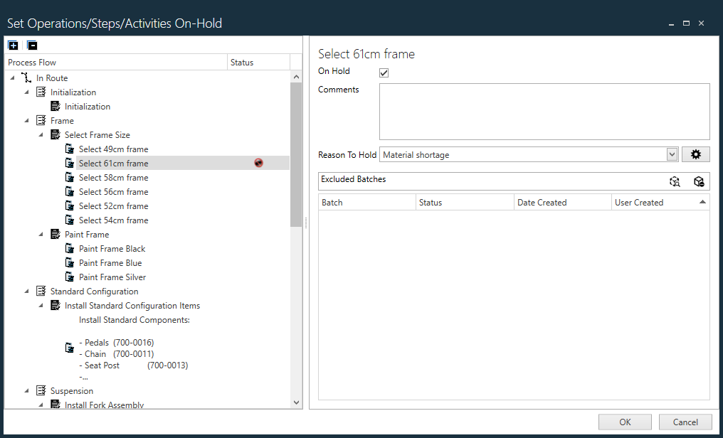
Displays the Set Operations/Steps/Activities On-Hold dialog where you can select operations, steps, or activities to place on hold.
On the left side of the dialog, select the desired operation, step, or activity to place on hold,.
On the right side of the dialog, select the On Hold check box and add any relevant comments about the reason for the hold in the Comments area.
The item you selected to hold displays a red Hold icon next to it in the tree. and new options are displayed on the right side of the dialog.
Use the Reason to Hold drop-down to select the reason for the hold (Material Shortage, for example).
To manage hold types, select the gear to the right of the Reason to Hold drop-down.
In the Hold Types dialog, use the Add Resource Type, Delete Resource Type, and Edit Resource Type buttons to add, delete, or edit hold types and (optionally) select a default hold type.
After making the desired changes, select OK to return to the Set Operations/Steps/Activities On-Hold dialog.
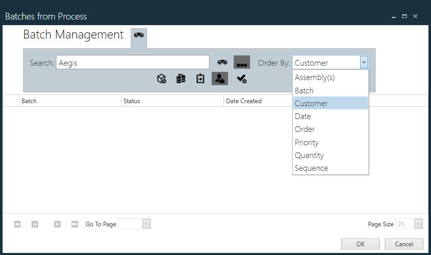
In the Set Operations/Steps/Activities On-Hold dialog, select the Search Batches button to the right of Excluded Batches to display the Batches from Process dialog where you can locate and select batches to be excluded from the hold.
Select the ellipsis (...) to the right of the Search field to display options for searching.
Use the Search options (By Assembly, By Batch, By Order, By Customer, and By Activation Date to help you locate the batches to be excluded from the hold.
Use the Order By: drop-down to select how the Search results are displayed.
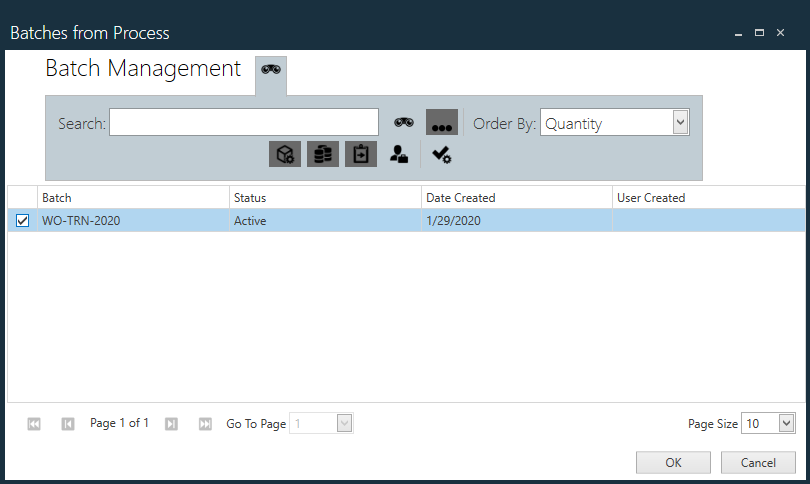
Use the check boxes to select the batches to exclude from the hold, then select OK.
The batches you selected are displayed in the Set Operations/Steps/Activities On-Hold dialog.
Note
If you need to remove a batch that was selected to be excluded from the hold, use the Remove Batch button on the right side of the Excluded Batches area of the dialog.
To complete your hold settings, select OK to return to the Process Definition window.
JavaScript errors detected
Please note, these errors can depend on your browser setup.
If this problem persists, please contact our support.