Color Coded step
Create a Color Coded step
A Color Coded step automates the color coding of parts to be placed or inspected and is typically used in PCB manufacturing. A Color Coded step type is used when some degree of automation needs to be added to the step and activity documents in the form of an active work instruction as shown in the following illustration. Color coded visuals are generated dynamically within a Color Coded step.

Tip
You can also use a wizard to quickly create a Color Coded step for a new operation. See Create a step using a wizard for details.
Log into the NPI client application.
Open a new process definition and create a new operation. (See Add a new operation to a process flow for more information.)
Double-click the operation to open it for editing.
Select the Add button under Step List in the Process tree, then select Color Coded Step.
Double-click the Color Coded step to open the Settings dialog.

Use the following tables to make your selections for the step on each tab of the Settings dialog.
When you're finished making selections for the step, select OK to confirm your choices.

Settings dialog - Basics tab
Option | Description |
|---|---|
Name | The name of the step.
For details about creating and saving step templates, see Create a process, step, or operation template. |
Default Instruction | Enter the default instruction for this step. |
Operator Interface Template | The Operator Interface template to apply to the step. See Operator Interface templates for more information. |
Assigned Workstation | The assigned workstation where the step and activities will be performed by a shop floor operator. See Create a factory and set up factory resources for more information. |
Any Order Mode (Activities can be viewed in any order) | All the activities associated with the step may be viewed in any order. |
Is Step Required? | The step cannot be skipped by a shop floor operator. |
Activities may be executed without starting a unit | Any activities associated with the step may be executed by a shop floor operator without first scanning or entering a UID to start the unit in production. |
Frequency |
|
Do you want to require credentials? |
|
Approval Process |
|
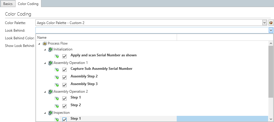
Settings dialog - Color Coding tab
Option | Description |
|---|---|
Color Palette | The color palette to use for color coding parts. Select a color palette from the Palette Chooser drop-down. Tip You can save custom color palettes for later use which can save you valuable time when creating future process definitions containing color coded steps.
|
Look Behind | The Look Behind feature is typically used in manual assembly operations where an assembler is shown the parts placed by the previous operator so that their work can be verified prior to performing their own tasks. Parts placed by the previous operator are color-coded/highlighted using a pre-selected Look Behind Color.
|
Look Behind Color |
|
Show Look Behind |
|

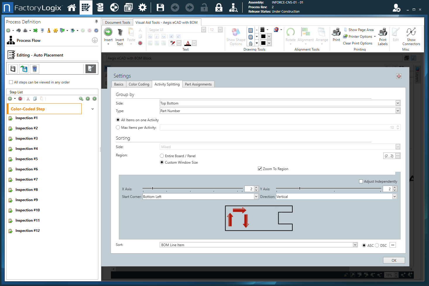
Settings dialog - Activity Splitting tab
The Activity Splitting tab of the Settings dialog for a Color Coded step allows you to define or limit the number of color-coded parts to be displayed on each page. (Since the human eye can typically discern about 10 different colors at any given time, it is best to limit the Max Number of Items per Activity to no more than 10.) On this tab of the Settings dialog, you can also define the ordering and sorting of parts listed for each activity to help focus operator attention on a specific area of a PCB for placing or inspecting parts.
Option | Description |
|---|---|
Group by |
|
Sorting |
|

Settings dialog - Part Assignments tab
Option | Description |
|---|---|
Color Assignments by |
|
Use Operation Assignments |
|
Use Custom Step Assignments |
|
Show Entire BOM  | When you select the Show Entire BOM  |

Settings dialog - Option Codes tab
Option | Description |
|---|---|
Option Codes | Displays a list of available option codes. Note Option codes are only used with configurable (CTO) assemblies.
Note For details about option codes, see Option codes for configurable assemblies. |
Assigned Option Codes | Displays the option codes assigned to this step. |
Use Logical Expression | Select the Use Logical Expression 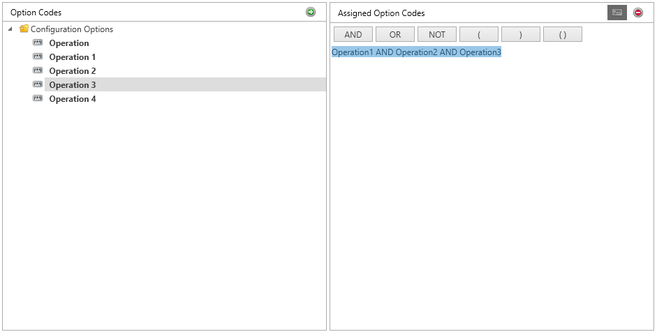 |

